This week we focused on actually designing a circuit board by adding an LED and a button to the Echo Hello World board and then we milled it.
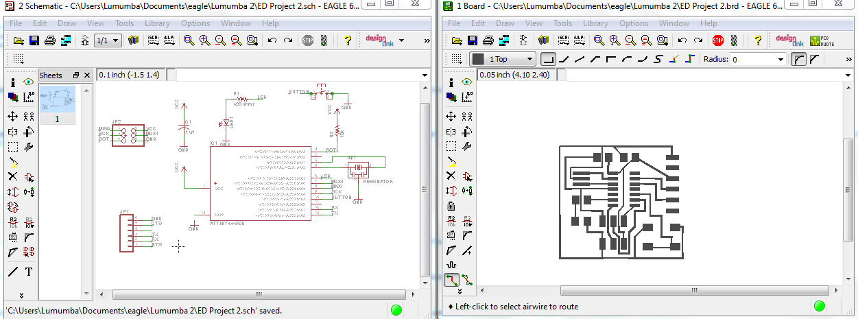
I decided to use Eagle in order to design my board. I used the schematic view in order to choose which parts to use from the various libraries and to also create the connections between different parts of the board, and I used board view in order to route the traces.
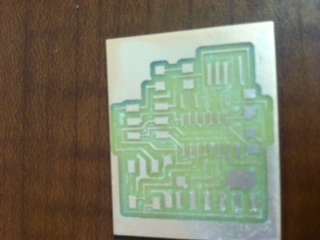
I exported the traces from Eagle as a monochrome png and it opened the file in Gimp. I did this so that I could convert the picture to greyscale so that fab modules could interpret the lines that the Modela MDX40 should cut. In Gimp, I scaled the area surrounding my traces down so that I would have a lot of extra space on my board, and I also made a png of just an outline to be cut out around the traces. I sent the traces and outline to the Modela MDX40, which then milled the board.
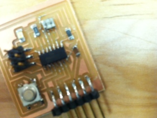
After milling the board, I then compiled the pieces and soldered them on.
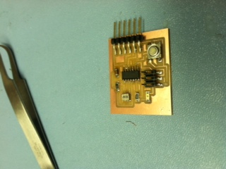
However, I realized that I had a couple of components netted together improperly, so I went back to Eagle and went through the previous steps again. After all of the components were soldered onto the new board, I performed a continuity test function with a multimeter in order to assess whether or not all of the components were properly connected. At that point I realized I had mad a mistake (again): I had not connected the GND on the microcontroller (pin 14) to anything. Instead of remilling the entire board, I attached the GND pin to the capacitor using a small wire.